Apantec Ionizing Radiation Sensors Testing Protocol
The objective of this testing procedure is to test the functionality of the Apantec ionizing radiation detection equipment and interlocks.
Starting Conditions
All rate meters are in normal operating condition.
Only the NORMAL condition LED is on. ALARM, ALERT, and FAIL LEDs are off.
There is no audible alarm from the rate meter.
The displays on the rate meters do not display any error messages.
All probes are calibrated.
Hutch-1 Front
Hutch-1 Black
Laser-1
RF-1
Vault-1 Control
Vault-1
The Ionizing Radiation Interlock protocase AREA MONITOR RADIATION lamps are green.
Vault-1 Control
Hutch-1 Control
The yellow and white contact blocks in the Vault-1 Control west aggregator panel for the radiation chain should have 24VDC across them.
Hutch-1 is in a non-secure state.
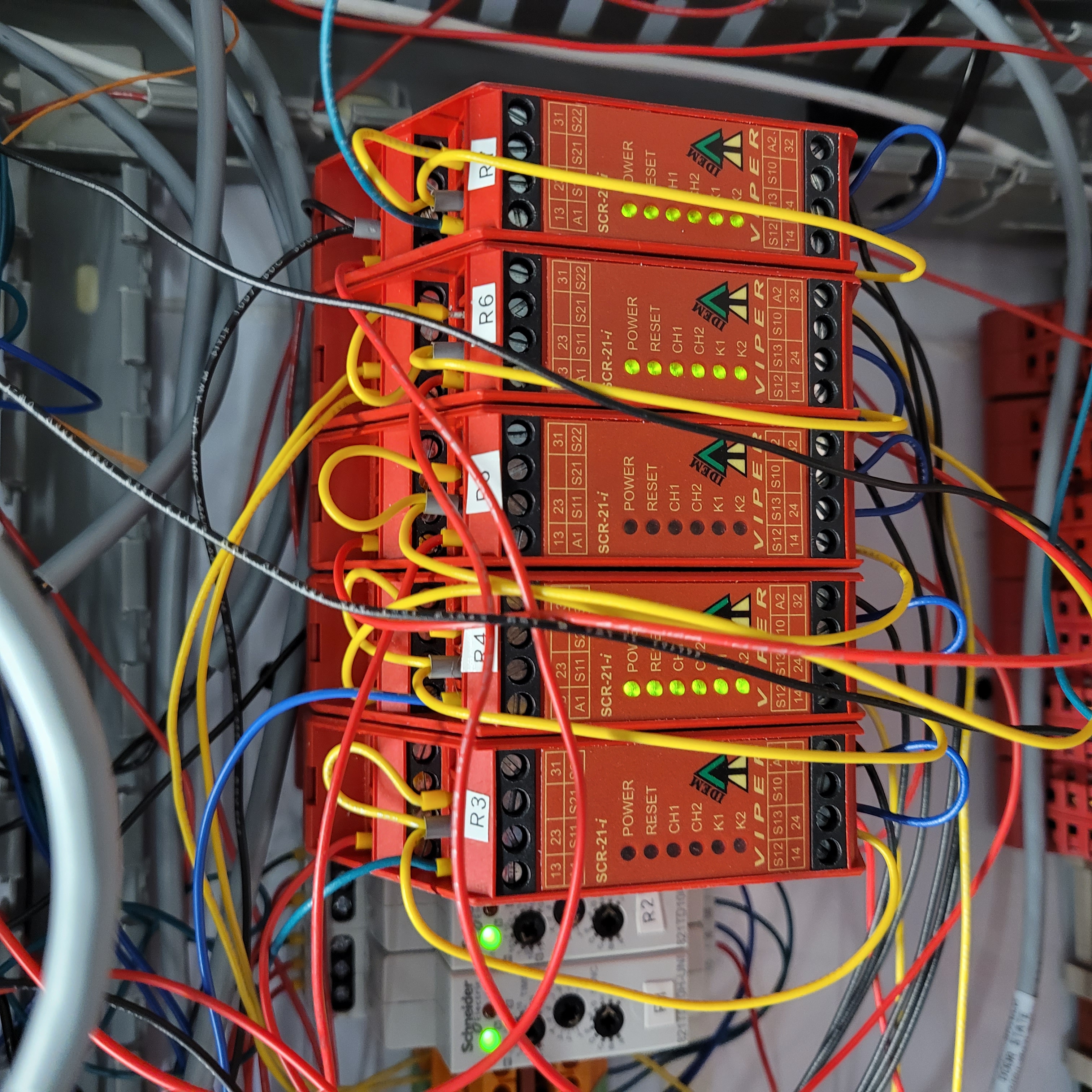
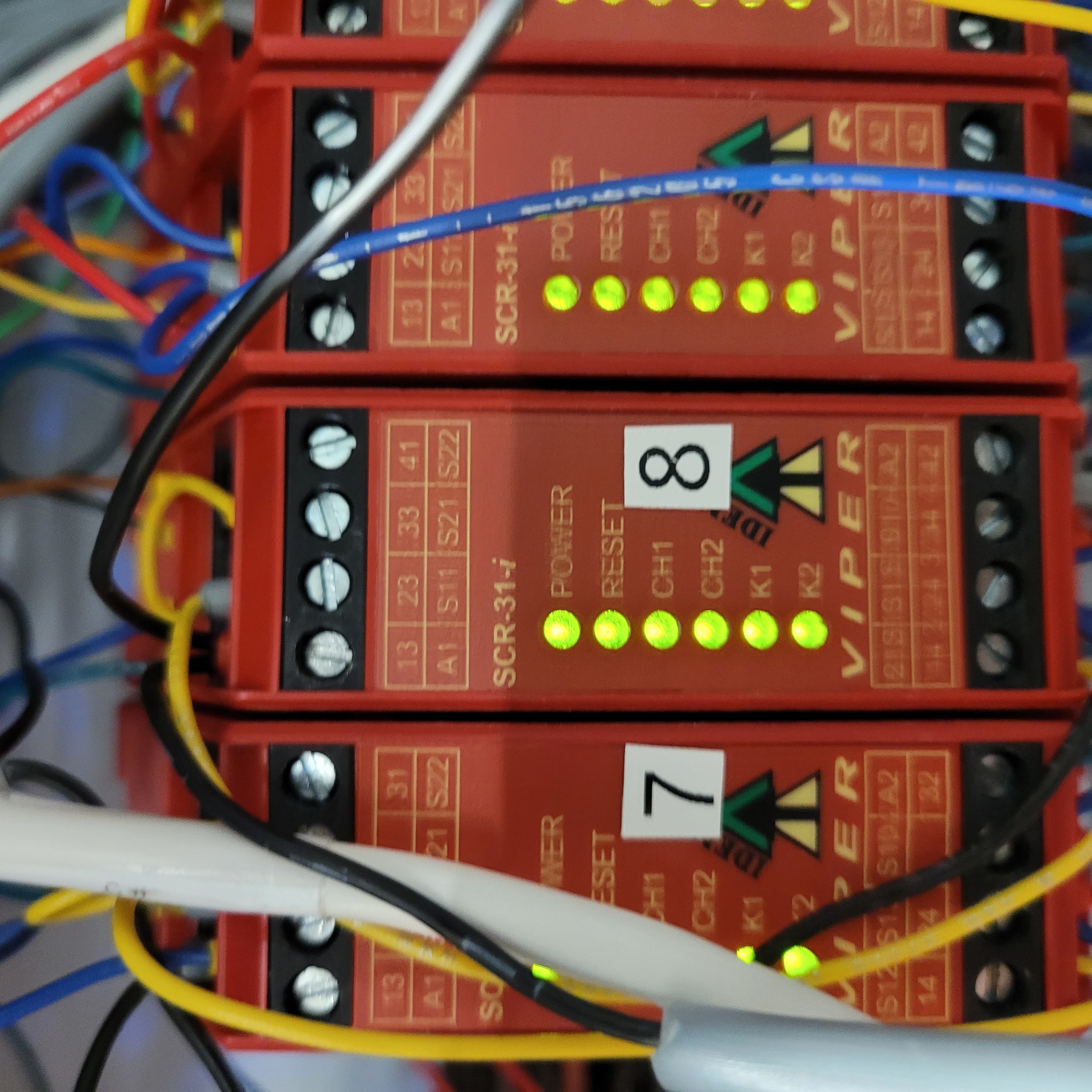
Relays in the Vault-1 Control west aggregator panel shows all diagnostic LEDs on.
R4
R6
R7
8
Relays in the Vault-1 Control west aggregator panel show no power.
R3
R5
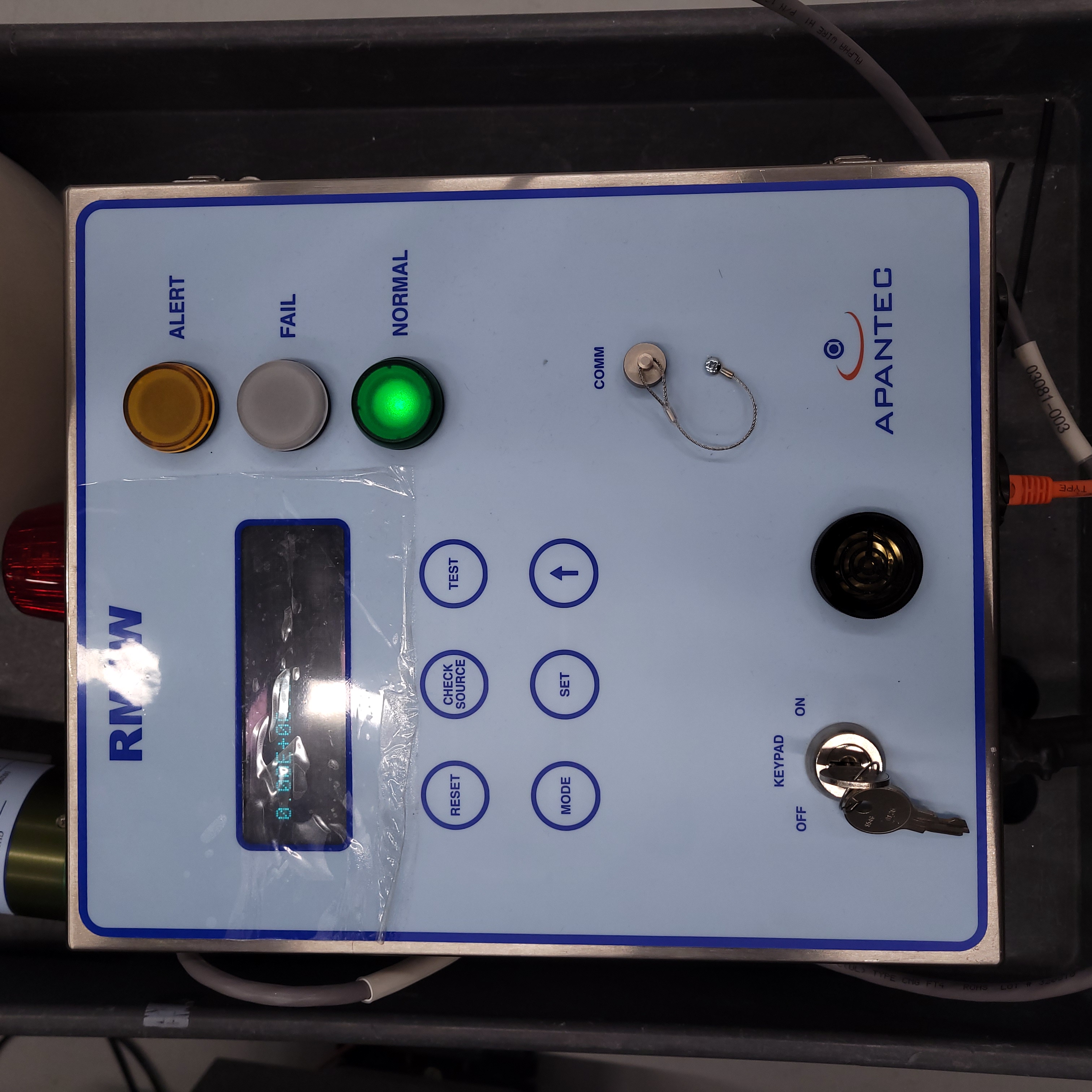
Figure 1: This is an example of the RMW1 rate meter control in a normal operating state.
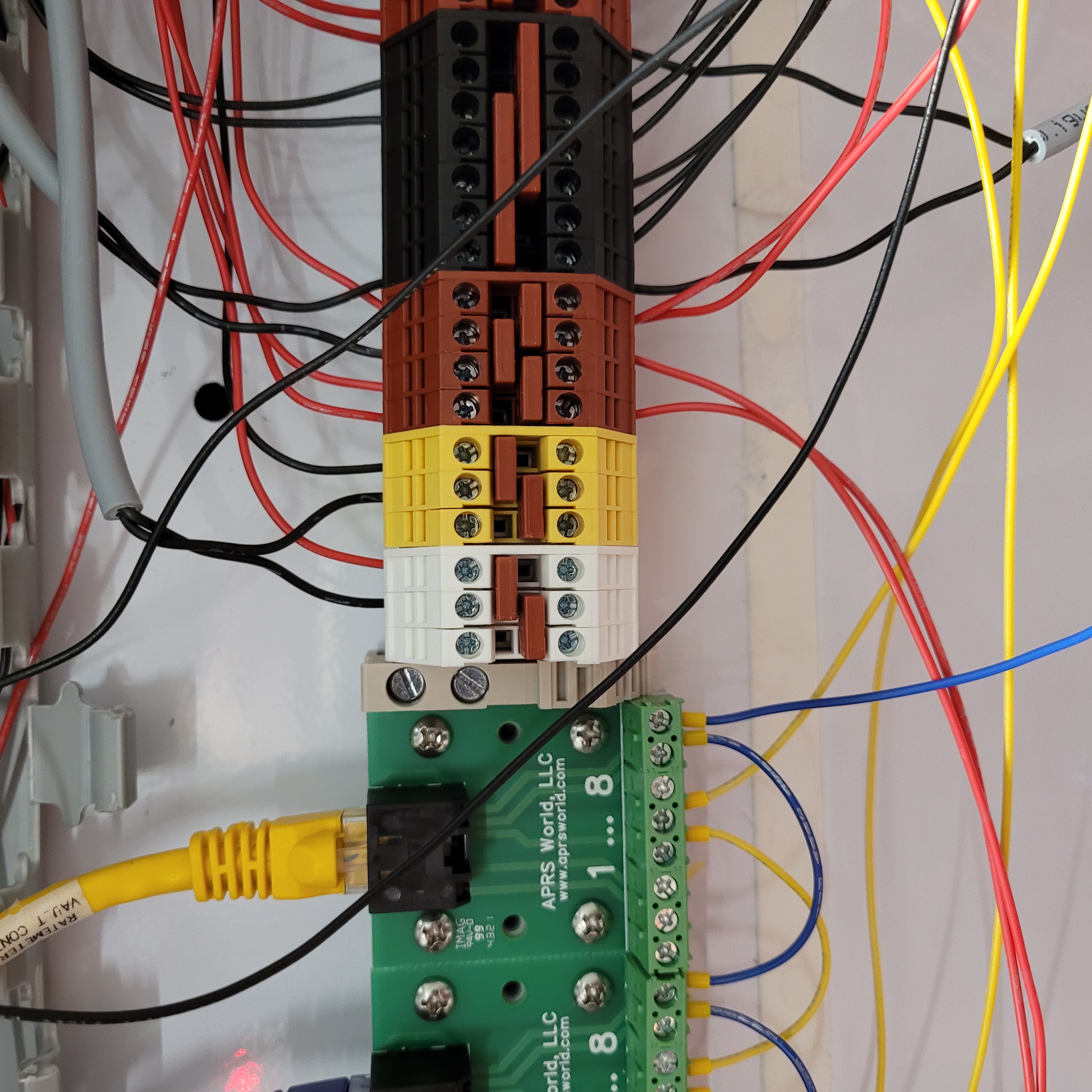
Figure 2: These are the yellow and white contact blocks in the Vault-1 Control west panel.
|
|
Relays R3-R8. ===================================================================== |
Relay 8. ========================================================================== |
Figure 3: These are the relays that correspond to the radiation chain in the Vault-1 Control west panel. Note that these relays are different from the ones referenced in the Vault-1 Ionizing Radiation Testing Protocol.
Testing Alert alarm
Using either the radiation monitoring program of using the Apantec physical interface, change the alarm set points to 0. In response:
The rate meter that controls the probe has the ALERT LED on.
The Ionizing Radiation Interlock protocase AREA MONITOR RADIATION lamp turns red.
The yellow and white contact blocks lose 24VDC across them.
Manually change the alert set point back to 50.
Gamma: |
Neutron: |
|---|---|
Hutch-1 Front |
Hutch-1 Front |
Hutch-1 Black |
Hutch-1 Black |
Vault-1 Control |
Vault-1 Control |
Laser-1 |
N/A |
RF-1 |
N/A |
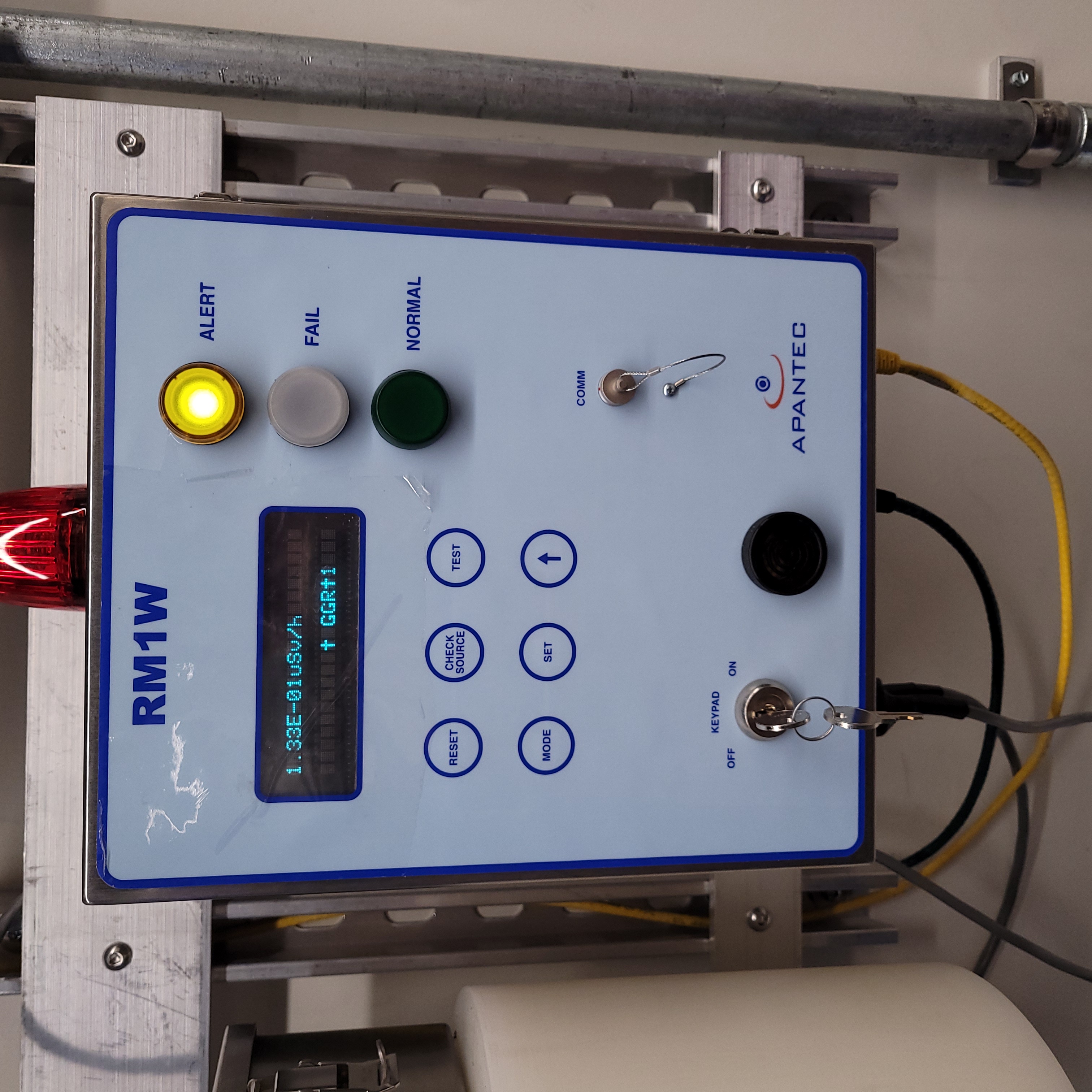
Figure 4: This is an example of the RMW1 rate meter control in an alert state.
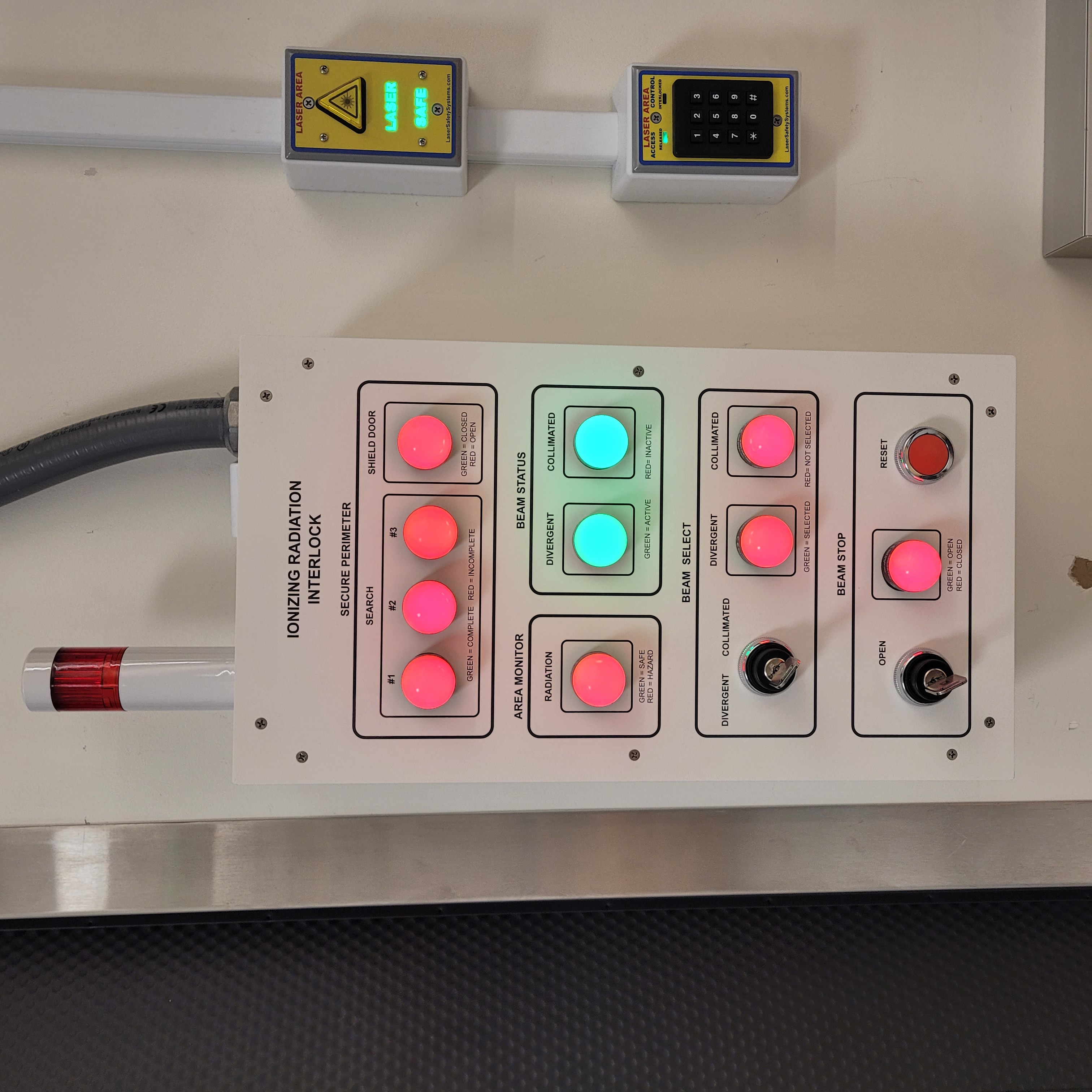
Figure 5: This is an example of the Hutch-1 Control IONIZING RADIATION INTERLOCK protocase AREA MONITOR RADIATION lamp in a fail state. This should occur on the Vault-1 Control IONIZING RADIATION INTERLOCK protocase AREA MONITOR RADIATION lamp as well.
Testing High Alarm
Secure Hutch-1. In Vault-1 Control west panel, relays R3 and R5 should have power, and relay R4 should have no power.
Change the alert alarm settings on any of the Hutch1 probes to zero. Nothing should happen, change the value back.
Using the same methods as with the alert alarm setting, change the high alarm setting to zero on each probe one at a time. In response:
The rate meter that controls the probe has the HIGH ALARM LED on.
The rate meter that control the probe has an audible alarm.
The IONIZING RADIATION INTERLOCK protocase AREA MONITOR RADIATION lamps turn red.
The yellow and white contact blocks lose 24VDC across them.
Manually change the set point back to 500.
Relay 16 in Hutch-1 panel loses power.
Gamma: |
Neutron: |
|---|---|
Hutch-1 Front |
Hutch-1 Front |
Hutch-1 Black |
Hutch-1 Black |
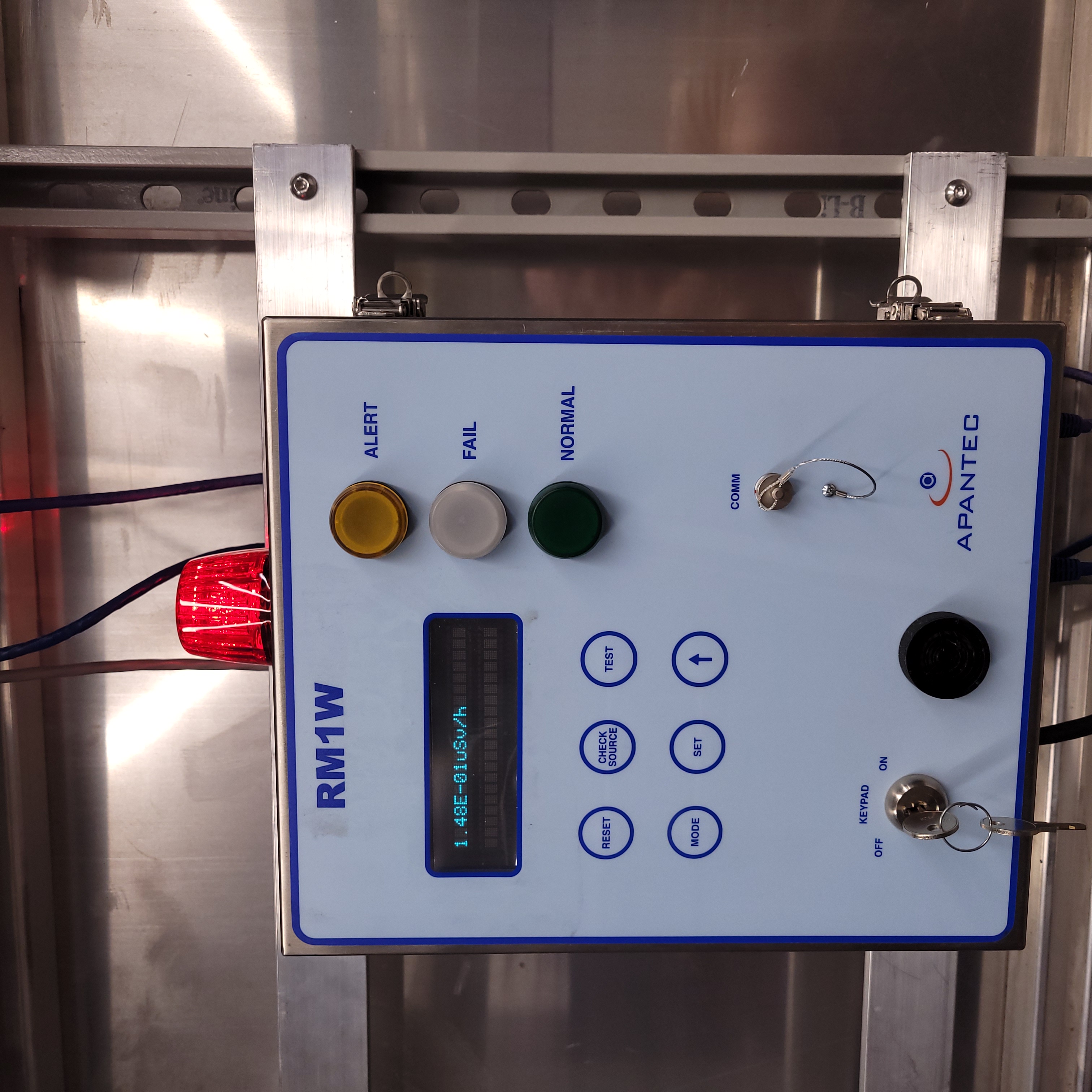
Figure 6: This is an example of the RMW1 rate meter control in an alarm state.
Emergency Tungsten Shutter Crash
Secure Hutch-1.
Set the BEAM SELECT to COLLIMATED.
Change the Apantec gamma probe high alarm set point to 0 in Hutch-1. In response:
Hutch-1 Control IONIZING RADIATION INTERLOCK protocase lamps for Beam Status turn red.
The COLLIMATED shutter (furthest, right side up shutter) is closed.