Narda Smarts II Microwave Sensor
The purpose of this procedure is to validate the functionality of the Vault-1 and Hutch-1 Narda Smarts II Microwave Sensor.
Starting Conditions
Narda meters are not alarming.
All meters are calibrated.
Vault-1
RF-1
Vault-1 Control IONIZING RADIATION INTERLOCK protocase MICROWAVE AREA MONITOR lamp is green.
Narda relay contact #10 in Vault-1 Control West aggregator panel LEDs are all on.
Yellow and blue contact blocks in Vault-1 Control west aggregator panel have continuity to each other.
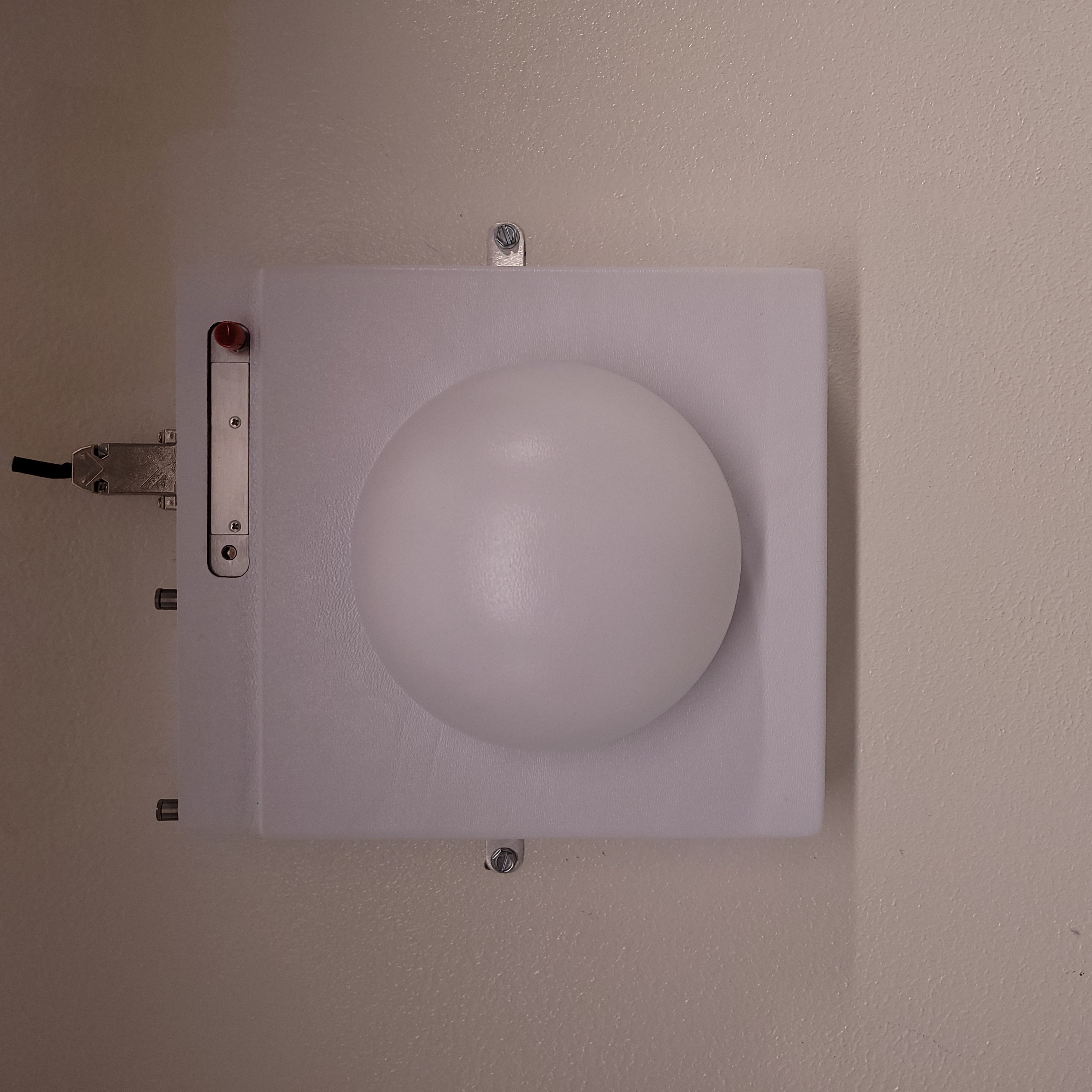
Figure 1: This is the Narda Smarts II Microwave Sensors. One is located on the Vault-1 north wall and the other is located on the RF-1 east wall.
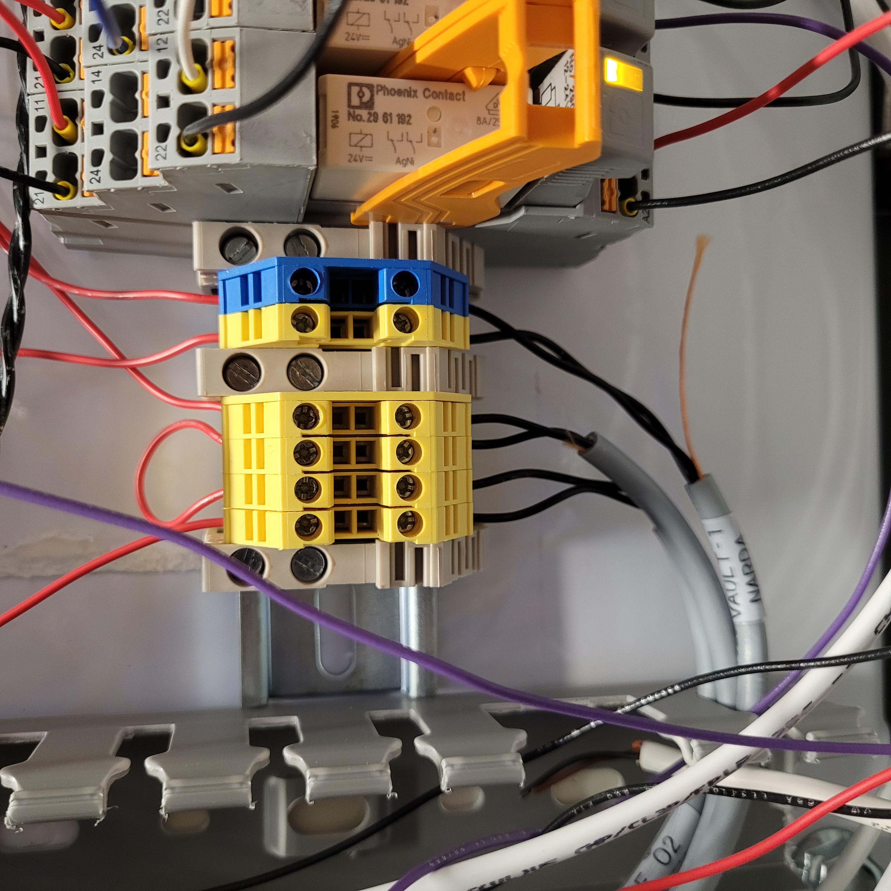
Figure 2: These are the yellow and blue contact blocks in the Vault-1 Control west panel that correspond to the Narda meters.
Testing
Go up to the Narda meter in RF-1and press the red test button. In response:
An audible alarm from the meter.
IONIZING RADIATION INTERLOCK MICROWAVE AREA MONITOR lamp is Vault-1 Control turns red.
Relay 10 in the Vault-1 Control west panel shows all diagnostic LEDs on.
Yellow and blue contact blocks will lose continuity with each other.
Repeat for Narda meter in Vault-1.

Figure 3: This is the Vault-1 Control IONIZING RADIATION INTERLOCK protocase MICROWAVE AREA MONITOR lamp when the Narda meter is in alarm. There is no lamp that corresponds to the Hutch-1 Control IONIZING RADIATION INTERLOCK protocase.